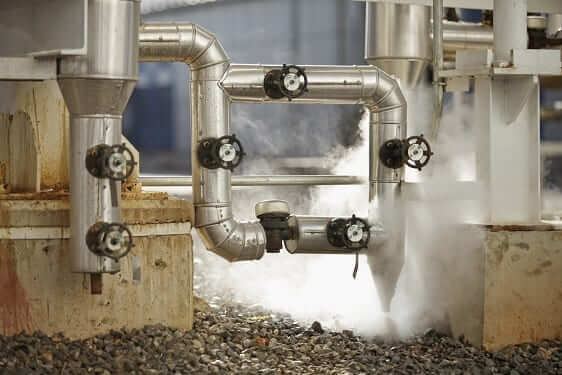
One of the enemies of quality steam in any system is condensate. A drip leg prevents this condensate from making its way through the steam system to the point of use.
Condensate occurs in piping due to radiant heat loss. Even with well insulated piping, you will still have some heat loss which causes some of your steam to condense. Without drip legs, your piping will eventually fill with condensate. This can cause water hammer, efficiency loss and even contamination.
How Drip Legs Work
Drip legs use the power of gravity to collect condensate. Because water is heavier than steam, it will flow to the low point in the system. In well-designed systems, this is where you will find the drip legs.
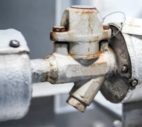 There are two components that make up a drip leg. First you will have a section of piping that drops down below the surrounding piping. This will allow for the collection of condensate from the system. Second, you will have a trap that allows for this condensate to leave the system without allowing steam to escape.
Where Are They Located?
Drip legs can be located in anywhere condensate may build up in the system, but they do have a few common locations. This includes one located just before the steam reached its destination. By putting a drip leg in this location, you can ensure any condensate is drained and pure steam reaches your process.
You will also find drip legs located at the end of your steam main. A good rule of thumb is that drip legs should be located at roughly 300ft intervals and no longer than 500ft intervals.
Finally, anytime there is an elevation change in your steam piping that is upward, you should have a drip leg. This is to collect any condensate that would collect in the low point caused by the piping going vertical.
How To Reduce Condensate Build Up
By ensuring all piping is insulated in the system you can reduce the amount of condensate that is produced. Next ensure there is no sag in the steam supply piping. Sag creates low points where condensate can sit. This can lead to water hammer, corrosion and a decrease in system efficiency. By supporting steam piping appropriately you can eliminate this issue.
Drip Leg Design
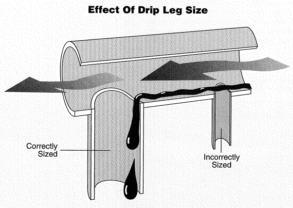
Image Courtesy of Armstrong International
In an article written by Armstrong International for Plant Engineering Magazine, they do a good job of discussing best practice for drip leg design:
“…for steam mains up to 4 in. in diameter, the drip leg should be constructed from the same size pipe as the main. For steam mains larger than 4 in., the drip leg should be half the diameter of the main but never less than 4 in. The distance from the bottom of the main to the top of the trap, in inches, divided by 28 yields the amount of static head, in psi, available to push condensate through the trap on startup. The accompanying table gives recommendations for sizing of steam mains and branch drip legs when the trap discharges to a gravity return.
On automatic startup, when return lines are elevated or pressurized, special precautions should be taken to prevent flooding. The best method is to collect the trap discharge in a no pressurized receiver and use a pump or a pumping trap to raise condensate or overcome back pressure.”
How to Reduce Condensate Build-Up
While drip legs are essential for condensate removal, preventing excessive condensate formation in the first place can further enhance system efficiency. Here are some ways to minimize condensate build-up:
Proper Insulation: Insulating steam piping can significantly reduce radiant heat loss, thereby minimizing the amount of condensate produced.
Eliminate Piping Sag: Steam supply lines should be properly supported to avoid sagging, which can create low points where condensate may pool. Sags increase the risk of water hammer, corrosion, and reduced system efficiency.
Speak To The Experts
In any steam producing system, you are going to have water that condenses as steam moves through the piping. (Even in well insulated ones.) If you do nothing to remove these water droplets, they can have negative effects on your system. Rasmussen Mechanical’s boiler experts can make sure your system is running efficiently and removing condensate like it should.